
Buildings / Clear-span arch structures
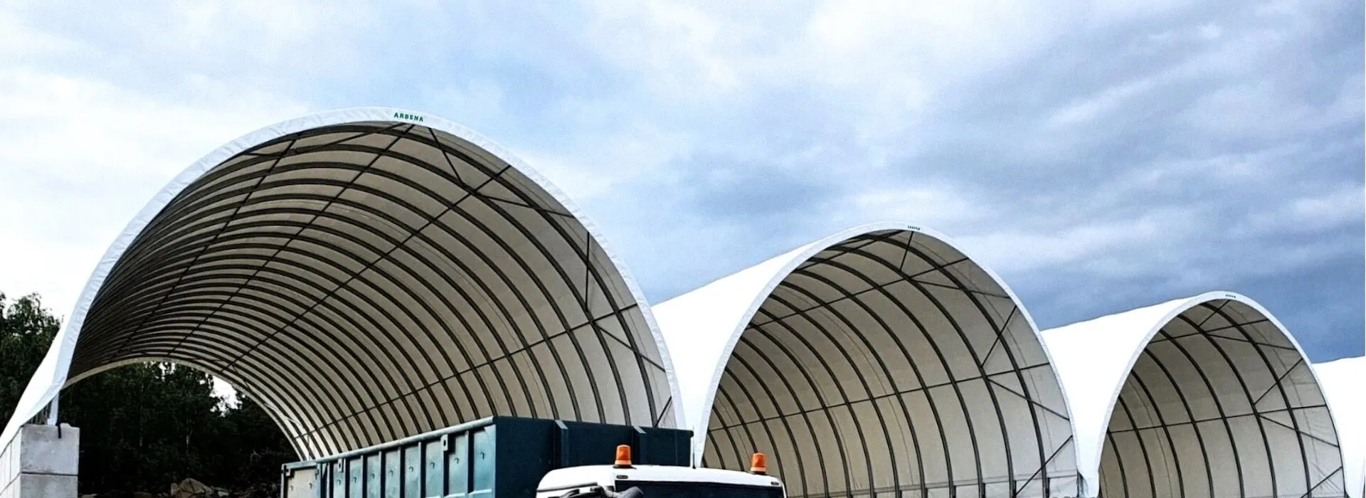
Clear span arch buildings up to 30 m
An unobstructed interior helps loaders, tipping vehicles and machinery move safely through the work area. ARBENA clear span arch buildings combine an engineered steel structure, tensioned membrane and anchoring selected for the ground and climatic loads.
- in the internal working area
- No columns
- span where technically suitable
- Up to 30 m
- steel structural profiles
- HX420
- calculated snow and wind loads
- By site
What it is and who it is for
Column-free interiors for loaders, tipping and bulk handling
In a clear span arch building, the roof is carried across the full width without internal columns obstructing storage or manoeuvres.
Clear floor area is especially useful where loading shovels, trucks, agricultural machines or forklift routes must operate close to stored materials. An arch profile can create generous internal volume without a row of intermediate supports.
Usable height changes across the curved section, so a nominal span is not enough to design gates, racking or tipping clearance. ARBENA evaluates the actual machines, loads, storage walls and access positions before selecting the geometry.

Business case
Why operators choose an arch structure

Uninterrupted floor area
No internal columns to interrupt loading routes, material bays or manoeuvring.

Span set by the operation
Building width and height are selected for the vehicles and handling method.

Bulk storage on concrete walls
An arch can be combined with suitably designed walls or concrete blocks.

Steelwork for the load zone
HX420 profiles and their spacing are chosen through structural calculations.

Practical enclosure options
Open gables, sliding gates and service doors can suit the operational flows.

Site-specific anchoring
The structure is attached to ground or engineered supports appropriate to the loads.
Data
Technical specifications
The building span, profile, arch spacing and fixing details are selected for the actual location. The figures below are not a substitute for project drawings.
| Parameter | Specification / project information |
|---|---|
| Building form | Curved clear-span steel-framed fabric building |
| Internal support columns | None in the clear-span working area |
| Span | Up to 30 m in certain configurations, subject to site calculations |
| Length | Modular bay arrangement to suit available site area |
| Steel | HX420 high-strength steel; FT profile according to selected frame |
| Corrosion protection | Magnelis® coating on current systems |
| Membrane | 670 g/m² standard PVC/PES, with a 650 g/m² fire-performance option |
| Ground support | Prepared ground, concrete or engineered retaining walls/blocks as assessed |
| Opening options | Open gables, sliding or lifting gates, service doors |
| Design actions | Local snow loads, wind exposure and national annex requirements |
Dimensions
Spans, heights and bay lengths
Standard agricultural catalogue widths include 6, 8, 10, 12, 15 and 16 m; larger industrial spans are possible only for an appropriate structure and location, up to 30 m. Clear height must be checked across the actual arch profile, not inferred from width alone.
-
 6 m wide
3.2 m high
Clear height 1.8 m at 0.5 m from the arch base
-
 8 m wide
4.5 m high
Clear height 2.3 m at 0.5 m from the arch base
-
 10 m wide
5.5 m high
Clear height 2.3 m at 0.5 m from the arch base
-
 12 m wide
6.5 m high
Clear height 3.3 m at 1 m from the arch base
-
 15 m wide
8.4 m high
Clear height 4.2 m at 1 m from the arch base
-
 16 m wide
8.2 m high
Clear height 3.4 m at 1 m from the arch base
Foundation options: ground anchors, concrete blocks and retaining walls
There is no universal foundation specification. Ground anchors require suitable soil and pull-out capacity; slabs, blocks and walls must be checked for the forces transferred by the frame. Storage walls also need to withstand pressure from the materials placed against them.
-

Concrete blocks Push walls and bay storage; the block wall becomes the side of the building
-

Retaining wall Minimum wall thickness 0.20 m for FT90 and 0.29 m for FT150
-

Shipping containers Fast cover on a yard with no civil works at all
-

Ground or concrete Soil, asphalt, road slabs or paving, with Terra-Lock® or HILTI anchors
Cladding, doors and natural lighting
Gables can be left open or fitted with doors and cladding. The size and position of openings are chosen around vehicle dimensions and flow. Translucent gable elements can introduce daylight when suitable for the design.
Covering and structure
- Structural steel
- HX420, micro-alloyed high-strength
- Corrosion protection
- Magnelis® ZM430, 35 µm per side
- Standard membrane
- Cross-woven PES with PVC coating, 670 g/m² (19.8 oz/yd²)
- Flame-retardant membrane
- 650 g/m², class B-s1,d0
- Tensile strength (weft)
- 2,500 N / 50 mm
- Temperature range
- −30 °C to +70 °C (−40 °C flame-retardant)
- Roof fire classification
- Broof(t1), ITB classification report
- Insulation
- Mineral wool, λ 0.04 W/(m·K), reaction to fire A2-s1,d0
- Membrane colours
- RAL 9010, RAL 7035, RAL 7026, RAL 6026
- Membrane warranty
- 10 years
Openings are specified at design stage, because the gable framing has to carry them.
Roller sliding gate

Double swing gate

Automatic gate

Service door

Applications
Where clear span buildings are used
Free internal width supports activities where moving vehicles and bulky stored materials must coexist.

Bulk aggregates
Material bays and access for wheel loaders.

Recycling
Sorting zones and vehicle circulation.

Industrial storage
Raw materials and finished products.

Agricultural machinery
Tractors, trailers and telehandlers.
Crop storage
Bales or grain with suitable ventilation and walls.

Construction
Covered materials and site machinery.
Logistics
Unobstructed transfer space.
Maintenance
Covered equipment working areas.
How we work, from enquiry to handover
We establish the building location, the machines that will operate inside, the preferred span and height, the handling method and any retaining walls. Structural loads and anchoring are then evaluated for the site.
After agreeing the layout, frame, doors and membrane, the structure is manufactured, delivered and installed. The schedule is confirmed for the project, not assumed from a catalogue estimate.
Process
From enquiry to installation
-
Your brief
Use, site, dimensions and practical constraints.
-
Engineering
Geometry, local loads, anchoring and options.
-
Manufacture
Components produced for the approved project.
-
Installation
Delivery and assembly according to the agreed programme.
Request a clear-span layout study
Tell us where the building will stand, what vehicles and materials it must accommodate, the required width, length, usable height and proposed base or retaining walls.